Friday 8 June 2012

Part Design

As compare to moulding, the following designing factors must be set.
1; gate and vent locations must allow or uniform filling of the cavity without melt jetting
or air entrapment.
2; the ejection area must be of sufficient size and location for uniform ejection of the
part without damage to it.
3; side sections must have ample draft for ease of ejection.
4; undercuts must be carefully designed with well rounded corners and draft angles to
allow uniform part remoulding without damage.
5; changes in wall thickness should be kept to a minimum or made gradually. Sharp
variations in wall thickness will result in variations in wall cooling rate, causing
war page.
6; ribs, bosses or fillets should be made thin to avoid sink marks on the surface of the
adjoining section, and to keep from increasing cycle time.
7; fillets should be placed at sharp corners to decrease stress concentration. Generally a
fillet radius to wall thickness ratio of - 0.6 is sufficient.
8; length of the flow paths must not exceed the flow ability of the resin selected for the
application.
Mechanical strength, appearance and function ability will also be affected by the design of
the various features of the part, for example :
Injection moulding

Sunday 3 June 2012

Screw & Barrel Design

Screw & Barrel Design
Screw design varies widely depending upon the manufacturer. Almost all machines are
being made with single flighted standard type screws with one manufacturer using a
doublewave type of barrier screw.

1; flight land width : 0.1 (screw diameter)
2 flight/cylinder clearance : 0.001 (screw diameter)
3 screw length/diameter ratio : commonly 20-25 : 1
4 feed/transition/metering sections : typically the screw length will be divided 50%
feed, 25% transition and 25% metering.
5 materials : screws are frequently made from AISI 4140 heat treated steel. Flight
tips are usually hard surfaced with Stellite. Chrome plating of the screw is
common, for ease of cleaning. Barrels are normally bimetallic, with an Hastalloy
inner lining for wear resistance.
6;flight pitch : almost always square (0 = 17.7o)
7 mixers : some type of mixing device is frequently added to the screw to improve
melt homogeneity and pigment dispersion. Since pigments are commonly added
in the form of a masterbatch, a high-shear mixer is required to improve dispersion
(Maddock type).
8 compression ratio : C.R. is in the range of to 4 : 1; most commonly 2-3 : 1

9 check valve : screws are equipped with a one way valve at the tip to prevent melt
from flowing back through the screw during the ram injection stage. Two most
common types in use are the ring type and ball type.
10 injection nozzle : the function of the nozzle is to convey the melt from the
injection cylinder to the mould, with minimum pressure drop and heat loss.
Nozzles are generally kept short, with open streamlined flow passages to
minimize pressure drop and heat loss and to avoid material hang-up

Mould Cooling

Mould Cooling
It is necessary to remove heat from the part to freeze it and cool it below its softening
temperature before it can be remove. It is important to remove the heat rapidly, for fast
cycle time, and evenly to prevent warpage related to uneven crystallization. In multicavity
moulds, cooling must be uniform in all parts.
Mould temperature is controlled by circulating cooling water through conduits in the
mould. Cooling conduits must be carefully placed in the mould to ensure even cooling of
the part.
Hot spots may be encountered in areas around gates, due to shear heating, or in areas of
the mould which are difficult to reach with cooling conduits. Special metal inserts may
be used in these areas, made from material with high heat transfer rates, such as
beryllium copper.
Separate cooling channels can also be installed in these areas, operating with higher flow
rates or lower temperature cooling water than the rest of the mould.

Ejector Systems

Ejector Systems
Some force must be applied to the moulded parts to eject them from the mould.
Mechanical knock-out devices such as pins or sleeves can be used, driven by the
movement of the mould as it opens.
With mechanical ejectors, the area of the knock-out device in contact with the part must
be large enough to avoid damaging or stressing the part.
In designing the part and the mould, side wall taper should be included to assist part
ejection. For polyethylene, a draft angle of 0.5 - 1o is recommended.

Mould Venting


Mould Venting
At the start of the injection cycle, the mould cavity have an air which must be vented as
it is displaced by the incoming melt. Inadequate venting can result in considerable
compression and heating of the trapped air, resulting in slow filling, poor welds and
possible burning of the resin.
Vents are located at the end of flow paths, most often in the parting line but also around
ejector pins.
Vents must be large enough to allow free passage of air, but prevent the passage of melt

Gate Dimensions

Type of gate
Gate Dimensions
Small gates will result in high injection melt temperatures and pressures. Large gates
will increase the time required to seal the gate area, increasing cycle time, and can result
in non-uniform filling in multi-cavity moulds.
As a general rule. the gate area should not be less than 1.25 mm, and the maximum
diameter or thickness of the gate should not exceed one half the thickness of the part at
the gate point. Gate lands are generally about one half the gate diameter, for a circular
gate, and about 0.75 - 1.0-mm in the case of a rectangular gate.

Ring and Diaphragm Gates

Type of gate
Ring and Diaphragm Gates are used to produce cylindrical parts with good
concentricity and no weld lines. With a ring gate, the core can be registered in both
mould halves, preventing shifting.

Sprue or Direct Gates

Type of gate
Sprue or Direct Gates are used with single cavity moulds, generally for thick walled
parts. In this pressure control is not necessary and the gate can be enlarged to ensure ease
of filling and packing to avoid sinks.
Gates are also described by their location in the mould, for example edge gated, tab gated
or submarine gated.
1; tab gating : used where it is desirable to eliminate gate defects from the part. The
gate is located on a tab which is attached to the part and which is removed in a
finishing operation.
2; submarine (tunnel) gating : this is particularly suitable for automatic moulding
because the part automatically delegates when it is ejected from the mould.
3; edge gating : occurs at the side of the part. It is usually used with parts which are
manually finished.

Round Pin Point Gates

Types of Gates
Round Pin Point Gates are widely used for automatic moulding because of the ease of
demoulding. The gate should be sharp edged at the runner and flared at the part, to
encourage separation at the runner gate interface, rather than affecting on the part surface.
Most moulds used for polyethylene use this type of gate.

Location of Gates

The location of the gate is extremely important to the satisfactory operation of the mould.
Gates must be located so that air contained in the cavity can be vented through easily
placed vents, usually at the parting line.
Weld lines should be avoided by locating the gate so that the flow proceeds uniformly out
from the gate in the direction of the greatest dimension, and by choosing the correct gate
design.
Gates should not be located at any location which is flexed or subject to mechanical
stress since the gate area is normally a weak spot in the part, due to high residual stresses.
Gate or land length has a major effect on pressure drop through the gate. Gate lengths are
usually fairly short, to minimize pressure drop.

functions of a gate.

Restricted gates are used in multi-cavity moulds where they perform the
following major functions :
1; provide a point between the part and the runner with low mechanical strength,
allowing easy separation.

2; provide a point in the runner system with a large surface-to-volume ratio which
will freeze rapidly when flow stops, sealing the cavity.

3; create a back pressure in the runner system to promote equal filling of all cavities
simultaneously.

Gate design of a mould

A gate is the connecting section between the runner system and the part. Gates can be
relatively large, providing full flow to the part or can be of smaller cross section than the
runner, restricting and accelerating the flow. Large gates are used to mould large thick
parts, or to avoid surface blemishes which might be caused by flow patterns from small
gates. Restricted gates are circular in cross section and are about 1.5 mm

Saturday 2 June 2012

A three plate mould

A three plate mould permits move gating of multiple moulds and makes it easy to
readily choose the moulded part from the runner system. In this system, when
the mould first opens, the cavity plate and the moveable or force plate open
together releasing the runner system and breaking the gate. As the mould
continues to open, separation occurs between the cavity plate and the force plate,
releasing the part.

The hot manifold

The hot manifold mould is another form of the hot runner system where in the
plastic in the runners is kept molten by heat from electrical heaters inserted into
the runners, sprues and gates.

Cold Runner

Cold Runner two plate mould contain two plates containing the cavity and
core mounted on a stationery and a moving platen, A shot. A single cavity
can be centre-gated, but multiple cavities must be Move On to gated.

An insulated runner mould

An insulated runner mould is a form of hot runner in which the plastic in the
runner system is kept sin a molten state by its own sensible heat.

A stacked mould

A stacked mould is a type of three plate mould in which two sets of moulds are
placed directly over each other, or stacked, in order to double the number of
mouldings possible in each cycle, with only a minor increase in required clamping
force.

A hot runner

A hot runner mould is similar to the three plate mould apart from that the sprue and
runners are kept in a molten state by electrical heaters, so the runner system does
not have to be discharged with the part. In accession to eliminating regrind, hot
runner systems eliminate runner system cooling, time is eliminated from the
production cycle, and the shot size is decreased by the size of the sprue and
runners.

Injection moulding

Types of Mould

1; Cold runner two plate
2; Cold runner three plate
3; Hot runner "runnerless"
4; Insulated hot runner
5; Hot manifold
6; Stacked

Runner design

The runner is the conduit for the melt from the sprue to the gate. The cavities should be
placed in the mould in a way which minimizes heat loss and the effect of the runners on
flow, by keeping them as short and free of bends as possible. In cross section, a full
round runner is desirable because it has minimum surface to volume ratio,

Mould design

Mould design
A mould may have one cavity or several, even as many as 100, depending largely on part
size. Multi-cavity moulds normally produce identical parts, though one type, known as a
family mould is used to make assortment of parts later assembled as a single
Object.
The main structural mechanism of a mould are the mould plates, which, with the aid of
pins and bushings, lock together to support and align the internal working parts of the
mould.

origin of injection moulding

The marketplace witnessed a large growth in 1940 s during world war 2,as there was large need for cheap, mass-produced goods.

Another feature that makes Injection Molding appeal-able is that large variety of polymer fits this method. Resources are selected on the basis of the strength together with the function needed for that ultimate products. As per offered info, about 20000 different resources can be found for Injection Molding.

So plastic part design has authenticated a continual growth because its beginnings within the late 1800 s. The method has advanced from your constitution of combs and buttons to a vast array of goods for many industries such as automotive, medical, aerospace, significant consumer products, plumbing, packaging, and building.
Injection moulding

Injection Molding- A Device For Economical Large Scale Production

Injection Molding- A Device For Economical Large Scale Production
The most common action of shaping plastic resins can be a procedure identified as Injection Molding. It is a production action for producing elements from both thermoplastic and thermostatic plastic components. This approach is commonly used in production many different components locomote through the quite smallest component to total body panels of vehicles. It truly is carried out with the devices named Injection Molding machines. The process of molding arrives into play following designing is above.

Injection Moulding - An Innovative Technologies,


Injection Moulding Cycle

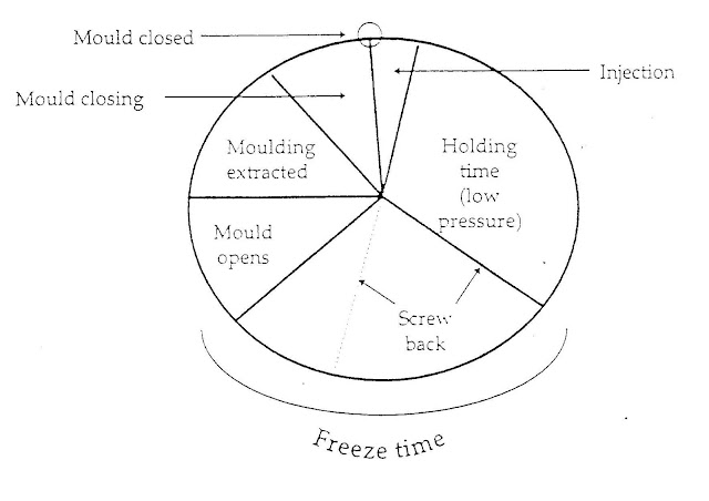
A typical sequence of Injection moulding cycle is as following

1; Starting with an empty cylinder, raw material from the feed hopper falls onto the rear
flights of the screw which takes material into the front of the cylinder. During its
passage along the cylinder it is plasticised to a fluid state with the help of external
heaters on the cylinder. Some material may escape through the nozzle but the back
pressure is generally sufficient to push the screw back in the cylinder and to provide a
holder for fluid plastic in the front of the cylinder for injection.

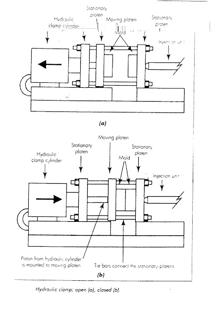
2; The mould closes and the cylinder moves forward on its way until the nozzle is in
contact with the mould access way.


3; The screw is moved forward by the hydraulic cylinder and the injection takes place.


4; After a short interval of time the screw rotates, creating some pressure in
the barrel, which forces it back against low pressure in the hydraulic cylinder, until
the limit switch operates, stopping the rotation. This plasticizes material ready for the
next shot.
5; The mould opens, the article is ejected and the mould closes again ready for the next
cycle.

Cycle of Operations

Mould discharge spray is sometimes used to remove the object from the mould. Due to
contours, ribs and undercuts, the object may get struck up in the mould.


Injection moulding

Advantages of Injection Moulding

1; Efficiency in weight of Object.
2; Choice of desirable surface finish and colors.
3; Choice of extreme strength of Objects.
4; Faster production and lower rejection rates.
5; Easily start-up and shut down procedures.
6; Less wastage.
7; Stability of processing range.
8; Versatility in processing different raw materials.
9; Option in Object sizes by changing the mould..
10;Minimum post moulding operations.

American injection molding

American Precision Products is a custom injection molding firm located in Huntsville, Alabama. They are experienced in molding thermoplastics, thermoplastic elastomers, and thermoset materials. They provide short and long molding runs for commercial and government applications.


Vulcan Industry

Vulcan Industry Co., Limited wasestablished in 1998 in Shanghai China, who has a long tradition of excellence. designs, engineering, and manufactures valueadded plastic mold and molded products. They uses the best machines and workers, they provide the best products at the lowest price to worldwide.
Vulcan is using international advanced CAD/CAM/CAE methods and integrated manufacturing systems to make the best quailty things.They are provided with more than 30 Injection Moulding making machines, including CNC machines, Digital-control EMDs and EWCs for Injection Mould fabrication. As well as over 40 Digital-controlled Plastic Injection Moulding machines for Injection Molded parts production. They are able to provide a full range of service from product design & manufacturing to accumulation & worldwide fast delivery.
Vulcan's injection moulding and plastic Injection Molded parts are widely used in auto accessories, Electronics, household appliances, medical devices, game players, and computer displays field

Materials used in moulding

Materials such as polystyrene, nylon, polypropylene and polythene can be used in a process called injection moulding. These all materials are thermoplastics so this means when they are heated and then pressured in a mould so they can be formed into different shapes as we want.